

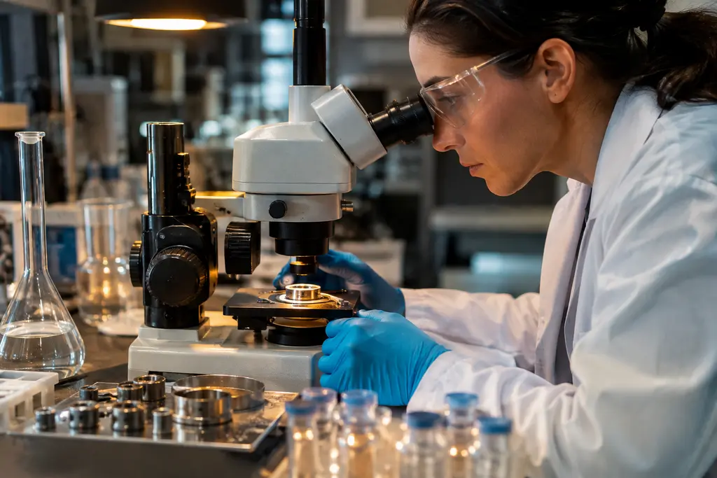
Large-Batch Catalyst Production for electrochemical CO₂ reduction is not only a question of making more catalyst powder. The harder specification problem is whether a larger batch can be converted into uniform electrodes that retain activity, selectivity, carbon use, and stability under industrially relevant operating conditions.
The available evidence supports a cautious reading. Reviews describe a gap between many laboratory demonstrations and the operating windows expected for commercial systems, especially in durability, current density, electrode area, materials supply, and stack integration. The issue is less about whether promising catalysts exist and more about whether they can be manufactured, coated, tested, and operated with repeatable performance at larger scale. A valuable resource for more insights into the industrial network involved is Mengo Industrial.
Why Large-Batch Catalyst Production Is Hard To Scale
Small catalyst batches can be screened quickly, but they do not always expose the same risks seen in square-centimetre to square-metre electrode formats. Electrochemical CO₂ reduction depends on catalyst chemistry, local pH, ion transport, gas access, membrane behavior, cell architecture, and product removal. A change in any one of those variables can change Faradaic efficiency, energy efficiency, or lifetime.
Lab Metrics Do Not Directly Transfer
Many laboratory studies emphasize Faradaic efficiency or partial current density under controlled conditions. Those data are useful, but they are not a full industrial specification. A review in Nature reported that many laboratory catalyst stability tests are around 100 hours, while economic viability is expected to require stability on the order of 3,000 to 10,000 hours Nature materials review. That gap matters because degradation mechanisms can be slow, cumulative, or linked to operating transients that short tests may not capture.
Industrial relevance is often associated with current densities at or above about 200 mA/cm² in flow cells or membrane-electrode assemblies. The challenge is that high current density on a very small active area does not prove that the same coating, ionomer distribution, pore structure, and water balance will work on a much larger electrode.
Large-Batch Catalyst Production And Electrode Uniformity
Large-Batch Catalyst Production becomes a coating problem as soon as the catalyst leaves the synthesis vessel. Roll-to-roll ink coating, screen printing, and slot-die coating are plausible scale-up routes, but each route introduces constraints on particle dispersion, solvent behavior, binder selection, drying, adhesion, and thickness control. A batch that appears chemically acceptable can still give uneven electrode performance if the deposited layer varies across the active area.
For multicarbon product targets, reported scale-up discussions point toward square-metre electrode areas and catalyst quantities far beyond milligram-scale synthesis. That creates a quality-control burden: manufacturers need to verify that particle size, phase composition, oxidation state, surface additives, and ink stability remain within an acceptable range from batch to batch.
Specification Gaps That Limit Industrial Readiness
CO₂ reduction catalyst specifications cannot be based on catalyst identity alone. A realistic data package needs to connect catalyst properties to electrode-level and stack-level measurements. Without that connection, procurement teams and technical evaluators may compare materials that were tested under incompatible conditions.
Durability And Current Density Targets
Durability remains one of the main filters for scale-up claims. Catalyst deactivation can arise from metal leaching, nanoparticle aggregation, contaminant poisoning, redox-state changes, and in-situ reconstruction. These mechanisms do not necessarily appear at the same rate under all electrolytes, membranes, humidification levels, or voltage profiles.
Electrode area is another source of specification drift. Research notes describe performance losses when moving from small cells to larger geometries, with non-uniform current distribution, overpotentials, and ohmic losses identified as contributors. That means a catalyst qualified on a small coupon may need a separate qualification step at larger electrode area before it can be treated as production-ready.
Carbon Use, Energy Efficiency, And Precious Metals
Carbon utilization is also a technical specification, not a secondary accounting item. In alkaline or neutral anion-exchange-membrane systems, a significant portion of CO₂ can form carbonate or bicarbonate rather than the desired product. Research notes identify 50–75% CO₂ conversion to carbonate or bicarbonate in such systems, with industrial single-pass CO₂ conversion benchmarks around 30% for C₁ products and around 15% for C₂+ products.
Energy efficiency adds another constraint. Reported values for C₁ products at industrial current densities are often far below the economic targets discussed in scale-up analyses, while C₂+ products face higher overpotentials and competing side reactions. Precious and critical materials compound the issue. The materials challenge is not limited to the cathode catalyst; membranes, anodes, ionomers, and stack hardware can also contain costly or supply-constrained inputs.
| Specification Area | Scale-Up Concern | Why It Matters |
|---|---|---|
| Durability | Short tests may not represent 3,000–10,000 hour expectations | Lifetime strongly affects replacement cost and uptime |
| Current density | Small-area results may not hold at larger electrode sizes | Throughput depends on stable operation at industrial current |
| Electrode uniformity | Coating thickness, porosity, and hydrophobicity can vary | Non-uniform zones can increase losses and degradation |
| Carbon utilization | Carbonate and bicarbonate formation reduce CO₂ efficiency | Feedstock loss affects separation and recycle design |
| Materials supply | Precious metals and critical inputs may limit deployment | Supply risk can influence cost and procurement strategy |
Manufacturing Controls For Larger Catalyst Batches
Large-Batch Catalyst Production needs controls that are closer to electrode manufacturing than to discovery chemistry. The specification should define acceptable variation in catalyst composition, morphology, surface state, residual impurities, ink behavior, loading, and coating quality. It should also define how those properties are measured.
Batch Consistency And Coating Methods
For technical buyers, the most useful data are not isolated peak performance values. More useful evidence includes batch-to-batch variation, coating repeatability, active-area mapping, electrode loading tolerance, and degradation under extended operation. If an ink coating method produces non-uniform hydrophobicity or binder distribution, gas and electrolyte access may vary across the electrode even if the catalyst synthesis was consistent.
Gas diffusion electrodes are a clear example. They must allow CO₂ transport while managing liquid water and electrolyte contact. Research notes identify flooding and loss of hydrophobicity as persistent concerns. Hydrophobic additives such as PTFE, flow-field changes, and pressure control are being evaluated, but these measures do not remove the need for electrode-level validation at relevant size.
Interfaces With Membranes And GDEs
The catalyst layer does not operate by itself. It is coupled to the gas diffusion layer, membrane, ionomer, electrolyte environment, and flow field. Anion-exchange membranes can degrade under hydroxide attack, and bipolar membranes can face delamination. If membrane resistance rises, the catalyst may appear less active even when the catalyst material has not fully failed.
This is why Large-Batch Catalyst Production should include compatibility testing. A catalyst batch that performs well with one membrane, binder, or gas diffusion layer may not perform the same way with another. For teams tracking adjacent scale-up work, the related analysis of CO₂ reduction catalysts covers similar durability and coating questions.
System Integration Is Part Of The Catalyst Spec
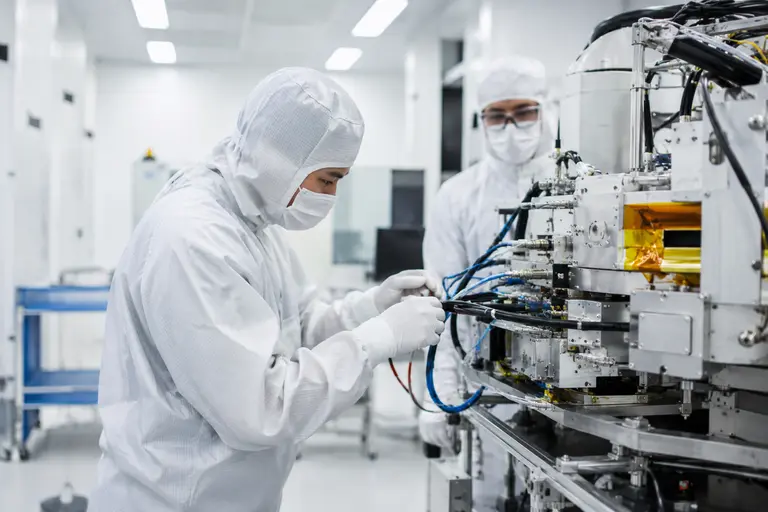
Electrochemical CO₂ reduction is often assessed at the catalyst or cell level, but the industrial bottlenecks extend across the full chain. A PubMed-indexed review frames industrialization around linked bottlenecks rather than isolated catalyst activity, including stack and system-level issues such as gas and liquid flow management, heat management, product separation, purification, and integration with intermittent renewable electricity PubMed review record.
Reporting Beyond Faradaic Efficiency
Faradaic efficiency remains useful, but it is not enough for scale-up decisions. Reports that omit charge balance, carbon utilization, energy input, cell voltage, active area, electrolyte conditions, and degradation rate are difficult to compare. For procurement and technical qualification, missing metadata can make two catalyst candidates appear more similar than they are.
A stronger specification would report operating current density, electrode area, catalyst loading, membrane type, cell configuration, CO₂ feed conditions, product distribution, single-pass conversion, energy efficiency, and stability duration. It would also state whether the result came from a small cell, a larger single cell, or a multi-cell stack.
Stack Balance And Downstream Separation
Large cells introduce distribution problems. Gas flow, liquid flow, temperature, pressure, and ionic resistance must stay within workable ranges across the electrode. Local dry-out, flooding, salt precipitation, or hot spots can shift selectivity and accelerate degradation. These risks are not solved by increasing catalyst batch size alone.
Downstream requirements also feed back into catalyst selection. A catalyst that produces a mixed product stream may create higher separation demand. A catalyst with lower carbon utilization may require more CO₂ recycle and carbonate management. Those system penalties should be treated as part of the technical assessment rather than as separate plant-design details.
Large-Batch Catalyst Production For CO₂ Reduction
Large-Batch Catalyst Production is best treated as an integrated materials, electrode, and system qualification problem. The evidence supports several near-term priorities: longer stability tests, larger active-area validation, tighter coating controls, clearer carbon-use reporting, and more transparent links between catalyst data and stack performance.
The current state should not be read as failure of electrochemical CO₂ reduction. It shows that promising catalyst chemistry has to pass stricter manufacturing and operating tests before it can support industrial claims. A credible scale-up package should show not only high selectivity in a small cell, but repeatable batch manufacture, uniform deposition, stable gas diffusion behavior, controlled membrane interfaces, and performance under conditions that resemble the intended operating system.
Large-Batch Catalyst Production therefore remains a specification challenge. The most defensible claims will be those that state the tested scale, operating window, duration, carbon balance, energy input, and known failure modes without implying that a laboratory result has already resolved manufacturing and integration barriers.